WELCOME TO PIPING TECHNOLOGY !!!

Hydraulic Schematic Symbols : How to read a hydraulic schematic symbol diagram

Contents

What are Hydraulic Schematic Symbols ?

Hydraulic schematic symbols are standardized graphical representations used to depict the components of hydraulic systems on schematic diagrams. These symbols allow engineers, technicians, and other professionals to communicate complex hydraulic system designs clearly and efficiently. Understanding these symbols is essential for designing, building, troubleshooting, and maintaining hydraulic machinery and systems.

Hydraulic systems are pivotal in countless industries such as aerospace, automotive, construction, and manufacturing. They utilize pressurized fluid to power various types of machinery, making them a preferred choice for applications that demand significant power and precise control. One of the critical skills for engineers and technicians working with these systems is the ability to understand and interpret hydraulic schematics. These schematics, which consist of standardized symbols representing components and pathways within the hydraulic system, serve as fundamental blueprints for constructing, maintaining, and troubleshooting hydraulic machines.

Introduction to Hydraulic Schematic Symbols

Importance of Hydraulic Systems in Various Industries

Hydraulic systems offer unparalleled power density and precise control, making them ideal for applications that require heavy lifting, precise movement, or sustained force. Industries such as construction rely on hydraulics for heavy equipment like excavators and loaders. In manufacturing, hydraulic presses perform tasks that involve molding, shaping, or cutting materials. The automotive sector uses hydraulics in braking systems and shock absorbers, emphasizing the system’s importance in safety and comfort.

Overview of Hydraulic Schematic Symbols

Hydraulic schematics are diagrams that depict the arrangement and relationship of components within a hydraulic system. These diagrams are vital for the design phase of system setup as well as during maintenance and troubleshooting tasks. By providing a clear and concise map of the system’s workings, these schematics allow for quicker diagnostics and more efficient system modifications.

Basics of Hydraulic Systems

To fully grasp the significance of hydraulic schematic symbols, one must first understand the basic components and principles of hydraulic systems.

Explanation of Hydraulic Principles

At the core of hydraulic systems is the concept that fluid under pressure can be used to transmit power. This transmission occurs through a confined fluid within pipes or hoses, transferring force from one point to another. The basic principles governing hydraulic systems include Pascal’s law, which states that pressure applied to a confined fluid is transmitted undiminished throughout the fluid.

Components of Hydraulic Schematic Symbols

Hydraulic schematic symbols represent the various components within a hydraulic system. These symbols are standardized to ensure clarity and uniformity across different diagrams and systems. Here’s an overview of the key components represented by hydraulic schematic symbols:

1. Pumps and Motors

  • Pumps: Symbols for hydraulic pumps often include a circle with one or more arrows showing the direction of the hydraulic fluid flow, which indicates the pump’s action (sucking and discharging fluid). Specific variations can denote different types of pumps such as gear, piston, or vane pumps.
  • Motors: Similar to pumps in shape, motor symbols also include circles but are differentiated by the direction of the arrows and additional markings that denote the type of motor (e.g., hydraulic, pneumatic).
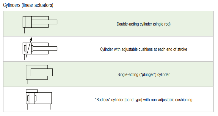
2. Cylinders

  • Single-Acting Cylinders: Illustrated with a single rectangle, sometimes with a spring shown on one end to indicate that the return motion is spring-actuated.
  • Double-Acting Cylinders: Shown with a rectangle that has two opposing arrows or connections, indicating that fluid can enter through either side to extend or retract the piston.

3. Valves

  • Directional Control Valves: These symbols consist of squares in line, each representing a position the valve can take. Internal paths within these squares show how fluid is directed in each position.
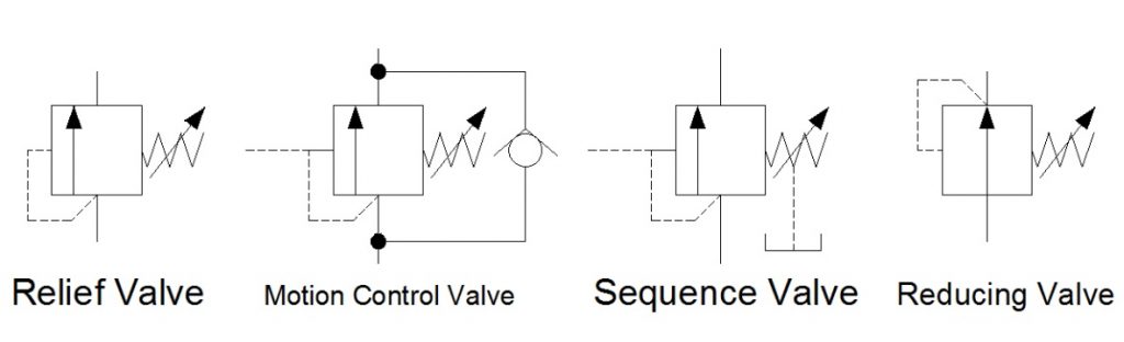
  • Pressure Control Valves: Include elements like an adjustable spring and an arrow through a line, indicating their function to regulate or limit hydraulic pressure.
  • Flow Control Valves: Represented with a gate-like symbol or an arrow intersecting a line, indicating their role in controlling the flow rate.

4. Reservoirs

  • Represented typically as rectangles, often simplified to indicate only the outline. A horizontal line inside the rectangle can represent the fluid level.

5. Filters and Coolers

  • Filters: Depicted by a circle with an internal pattern (like a grid) that signifies its role in removing particulates from the hydraulic fluid.
  • Coolers and Heaters: Illustrated with symbols that include internal squiggly lines or fan icons to represent the function of temperature regulation.

6. Accumulators

  • Shown as a rectangle divided by a diagonal or curved line, representing the separation of gas and liquid within the accumulator. This component stores energy in the form of pressurized gas.
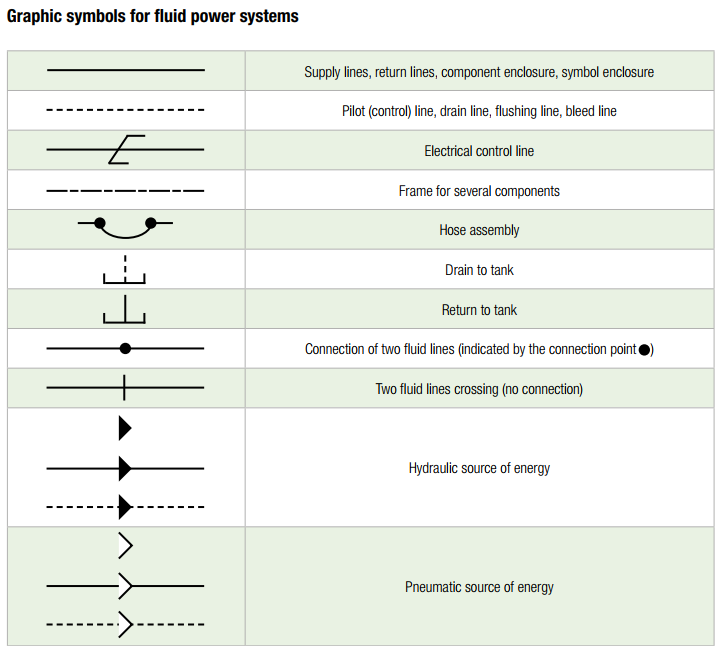
7. Pipes and Hoses

  • Lines: Solid lines represent hydraulic pipes or hoses that carry pressurized fluid. Dashed or dotted lines may represent low-pressure or return lines.
  • Connections: Various types of junction points are depicted to show how components like valves and pumps are interconnected.

8. Accessories

  • Pressure Gauges: Usually shown as a circle with a ‘P’ or ‘Psi’ inside, indicating their role in measuring the pressure within the system.
  • Heat Exchangers: Depicted with symbols indicating their role in cooling or heating the fluid.

Using Hydraulic Schematic Symbols

Understanding and using these symbols effectively allows technicians, engineers, and designers to quickly and accurately develop, analyze, and troubleshoot hydraulic systems. Each symbol conveys essential information about the function and operation of the component it represents, making it a crucial aspect of hydraulic engineering.

Understanding Hydraulic Schematic Symbols

Understanding hydraulic schematic symbols is crucial for anyone working with hydraulic systems, as these symbols provide a visual representation of the system’s components and operations. This knowledge is essential for designing, troubleshooting, and maintaining hydraulic systems efficiently and safely. Here’s a detailed guide to help you understand these symbols more comprehensively.

Importance of Hydraulic Schematic Symbols

Hydraulic schematic symbols are integral to hydraulic engineering, enabling clear and concise communication across different teams and disciplines. These symbols help in visualizing the system’s design and function, making it easier to identify components and understand how they interact.

Basic Principles of Hydraulic Symbol Interpretation

  1. Standardization: Hydraulic symbols are standardized according to international norms (ISO 1219) and national standards. Familiarizing yourself with these standards is the first step toward understanding hydraulic diagrams.
  2. Simplicity and Abstraction: Each symbol is designed to abstractly represent the physical components of a hydraulic system. While simplified, these symbols contain enough detail to identify the type of component and its function.
  3. Functional Identification: Symbols are generally grouped by function—such as pumps, valves, motors, and cylinders. Recognizing the group a symbol belongs to will guide you in understanding its role within the system.

Key Components and Their Symbols

  • Pumps and Motors: Represented by circles with arrows indicating the flow direction. Variations in the design specify the type of pump or motor (gear, piston, vane).
  • Cylinders: Illustrated by rectangles. A single line inside signifies a single-acting cylinder, while a double line denotes a double-acting cylinder.
  • Valves: Shown with a combination of squares and internal lines. The complexity of the valve’s symbol corresponds to its function and control type (manual, solenoid, pilot).
  • Reservoirs: Depicted as rectangles, often with a horizontal line to show the fluid level.
  • Filters and Coolers: Filters are circles with internal detailing, while coolers might include elements like a fan symbol to indicate their function.

Reading Hydraulic Schematics

  • Flow Paths: Follow the arrows. Arrows on lines and within symbols indicate the direction of fluid flow, which is crucial for understanding how the system operates.
  • Component Interactions: Analyze how components are connected. This will tell you how fluid moves between components and how the system’s parts interact functionally.
  • Operational States: Many hydraulic symbols, particularly valves, have multiple operational states. These are often depicted by several parallel symbols showing different flow paths.

Practical Tips for Mastery

  • Study Real Systems: Compare actual hydraulic systems with their schematic diagrams. This hands-on approach helps solidify your understanding of how symbols translate into physical components.
  • Use Simulation Software: Many modern engineering software tools allow you to simulate hydraulic systems. These simulations can help visualize how systems operate and how changes in the diagram affect functionality.
  • Continuous Learning: Hydraulic technology evolves, so staying updated with the latest advancements and changes in standard symbols is crucial.

Symbols for Hydraulic Pumps and Motors

Understanding the symbols for hydraulic pumps and motors is crucial, as these components are the primary drivers of fluid within the system. Here’s a breakdown of the common types and their symbolic representations.

Gear Pumps and Motors

  • Symbol: Gear pumps and motors are represented by two interlocking gears within a circle. The direction of the arrow within the symbol indicates the direction of flow, which corresponds to the rotation direction of the gears.

Piston Pumps and Motors

  • Symbol: These are depicted as a circle with one or more arrows pointing outward, symbolizing the radial motion of the pistons within these units. The number of arrows often indicates the number of pistons.

Vane Pumps and Motors

  • Symbol: Vane pumps and motors are shown with a circle containing a series of slanted lines or a star-like figure, representing the rotating vanes inside the pump or motor casing.

Symbol Variations and Their Meanings

Each variation in the symbol (such as the presence of additional lines or changes in arrow direction) provides specific information about the pump or motor, such as whether it is variable or fixed displacement, or the type of control it utilizes.

Symbols for Hydraulic Cylinders

Hydraulic cylinders are critical actuating elements, converting hydraulic energy into mechanical force. The symbols used in schematics help identify their action type and construction.

Symbols for Hydraulic Cylinders

Single-Acting Cylinders

  • Symbol: Represented by a single square with an arrow showing the direction of force application. This symbol indicates that fluid pressure is applied in one direction only, allowing the spring or external load to return the piston to its original position.

Double-Acting Cylinders

  • Symbol: Depicted with two opposing arrows within a square, showing that the cylinder can actuate in two directions, powered by hydraulic fluid on both sides of the piston.

Telescopic Cylinders

  • Symbol: Illustrated as a series of nested squares, each representing a stage of extension in the telescopic series.

Symbol Differentiation and Interpretation

The specific details and modifications in a cylinder’s symbol can inform about its features, such as cushioning, sensor presence, or special seals.

Valves in Hydraulic Systems

Valves control the flow and pressure within hydraulic systems, and their symbols are integral for understanding how operators control system functions.

Directional Control Valves

  • Manual: Shown as a valve symbol with an actuator lever.
  • Solenoid: Indicated by a square with a diagonal line and a circle at one end, representing the solenoid actuator.
  • Pilot-operated: Combines basic valve symbols with additional lines or symbols indicating pilot control.

Pressure Control Valves

  • Relief Valves: Typically depicted with an arrow that pierces a line, indicating the pathway for pressure release.
  • Pressure Reducing Valves: Shown as a valve symbol with an additional line that typically includes a spring symbol, indicating the control mechanism.

Flow Control Valves

  • Throttle Valves: Illustrated with an arrow intersecting the path, indicating adjustable flow restriction.
  • Non-return Valves: Depicted as a ball and a seat within a passageway, indicating the check function that allows flow in one direction only.

Complex Valve Combinations and Their Symbols

Valves are often depicted in combination to illustrate how they interact within the hydraulic system, showing series or parallel configurations, or integration with other hydraulic components.


Accumulators and Filters

Accumulators and filters are crucial for maintaining the efficiency and longevity of hydraulic systems. Their symbols help in identifying these components on schematics and understanding their functions.


Accumulators

  • Symbol: Represented by a rectangle divided into a fluid area and a gas area, typically with a curved line or diaphragm symbol separating them. This indicates the accumulator’s ability to store energy in the form of pressurized gas and release it when needed to maintain pressure or absorb shocks.

Filters

  • Symbol: Shown as a circle with an internal grid or diagonal lines, symbolizing the filter medium that cleans the hydraulic fluid by removing particulates and contaminants.

Operational Importance

Understanding the placement and type of accumulators and filters in a system is vital for troubleshooting and maintenance. These components ensure the hydraulic fluid is clean and the system operates under optimal pressure conditions.

Reservoirs and Fluid Conductors

The reservoirs and the conduits that carry hydraulic fluid are foundational to any hydraulic system, with their symbols indicating storage and flow paths.

Reservoirs

  • Symbol: Typically depicted as a rectangle, often with a horizontal line indicating the fluid level. This symbol may include additional features like temperature and level indicators.

Types of Lines and Their Symbols

  • Working Line: Represented by a solid line, indicating the main pathways through which the hydraulic fluid flows under pressure.
  • Pilot Line: Shown as a dashed line, used to denote smaller lines that control the operation of larger valves or systems.
  • Drain Line: Illustrated with a dashed line or a series of dot-dash sequences, indicating lines that return fluid to the reservoir without pressure.

Accessory Symbols

Hydraulic systems may include various accessories such as heat exchangers, sensors, and gauges. Their symbols are essential for a complete understanding of system functionality.

Heat Exchangers

  • Symbol: Depicted as a circle with internal squiggly lines, indicating the flow of fluid through a cooling or heating medium to regulate the temperature of the hydraulic fluid.

Sensors and Gauges

  • Symbol: Shown as circles or rectangles with specific marks or symbols inside, such as a “T” for temperature or “P” for pressure, providing real-time data crucial for system monitoring.

Symbol Interpretation for System Monitoring

Accurate interpretation of these symbols is critical for diagnosing issues and ensuring the system operates within its designed parameters.


How to read a hydraulic schematic symbol diagram

Understanding how to read hydraulic symbols is crucial for anyone working in fields that involve hydraulic systems, such as engineering, maintenance, and troubleshooting. Here’s a closer look at the basic principles, a detailed breakdown of the components, and practical tips for reading and interpreting hydraulic diagrams effectively.

Basic Principles of Hydraulic Symbol Interpretation

  1. Learn the Standards: Hydraulic symbols are standardized internationally (ISO 1219) and nationally (ANSI in the U.S.). Familiarize yourself with these standards as the symbols are designed to provide a clear, concise representation of hydraulic system components and their functions.
  2. Understand Symbol Categories: Symbols are categorized by component types, such as pumps, motors, valves, cylinders, and accessories. Recognizing the category of a symbol helps in understanding the role of each component within the system.
  3. Flow and Control Logic: Arrows in hydraulic symbols indicate the flow direction of the hydraulic fluid. Understanding how the fluid flows through the system and how it is controlled is essential for interpreting the schematics.

Detailed Breakdown of Symbol Components

  1. Pumps and Motors: Symbols typically consist of circles with arrows. The direction of the arrow indicates flow direction, distinguishing between pumps (fluid input) and motors (fluid output). Variations like multiple arrows can denote multiple stages or flows.
  2. Cylinders: Represented by rectangles, with lines indicating the direction of movement. Single lines suggest single-acting cylinders, while double lines denote double-acting cylinders.
  3. Valves: Complex symbols that can include squares connected by lines. The number of squares typically represents the number of positions a valve can hold, and the lines depict the flow paths. Additional details like arrows, T’s, or springs help indicate the type of valve (directional, pressure, flow control) and its operation.
  4. Accumulators: Shown as a rectangle divided into two parts, indicating the separation of gas and fluid. This symbol helps identify storage components in the system.
  5. Filters and Coolers: Usually depicted with a simple circle or a rectangle with internal symbols indicating the function, such as cleaning the fluid or cooling the system.

Practical Tips for Reading and Understanding Hydraulic Schematic Symbols Diagrams

  1. Start at the Power Source: Begin interpretation with the pump, which is the heart of the hydraulic system. Understanding where the power comes from helps in tracing the flow through the system.
  2. Follow the Flow: Trace the lines from the pump through various valves and actuators. This approach helps you understand the sequence of operations and the path of fluid flow.
  3. Identify Critical Components: Look for key components such as main control valves, pressure relief valves, and critical actuators. Understanding their symbols and locations within the circuit can provide insights into the system’s primary functions and safety features.
  4. Utilize Color Coding and Labeling: If available, use color coding and labels to distinguish between different pressures, flows, or other important attributes. This can simplify complex diagrams and make them easier to read.
  5. Check for Modifications: Always ensure that the diagram is up to date. Modifications to the system might not always be reflected in older diagrams, which can lead to confusion and errors in system analysis.
  6. Practice Regularly: The more you work with hydraulic diagrams, the more intuitive reading them will become. Practice by comparing real-world systems to their schematic representations to reinforce your understanding.

By mastering these basics, detailed components, and practical reading tips, professionals can significantly enhance their ability to work effectively with hydraulic systems, ensuring accurate design, maintenance, and troubleshooting.


Advanced Symbols and Applications

As hydraulic systems evolve, so do the symbols used to represent newer technologies such as proportional and servo valves. These components offer enhanced control capabilities and are essential in complex applications.

Proportional Valves

  • Symbol: These valves are typically represented by a standard valve symbol with an additional diagonal arrow across it, symbolizing the valve’s ability to control flow proportionally to an input signal.

Servo Valves

  • Symbol: Similar to proportional valves but often include more intricate features in the symbol to indicate higher precision and control, such as multiple stages or feedback loops.

Recent Updates in Symbol Standards

With advancements in hydraulic technology, new symbols are periodically introduced to represent innovations such as digital controls or integrated electronics. Staying updated with the latest standards is crucial for engineers and designers to accurately depict and interpret these advanced components.

Application in Complex Hydraulic Systems

Advanced symbols are increasingly found in applications requiring precise control, such as in aerospace for controlling flight surfaces, or in automated manufacturing lines where precision and repeatability are critical.

Troubleshooting Using Schematic Symbols

Understanding hydraulic schematic symbols is not only vital for design and construction but also plays a crucial role in troubleshooting system issues.

Common Issues Identified Through Schematic Analysis

  • Leaks and Pressure Drops: These can often be traced back to specific components such as valves or seals, which may be incorrectly represented or outdated on the schematic.
  • Component Failures: Symbols help identify the type and function of a component, aiding in pinpointing failures within the system.

Tips for Effective Troubleshooting

  • Systematic Approach: Start at one point of the system, such as the pump, and follow the flow lines through the system, checking each component as you go.
  • Check for Updates: Ensure that the schematic is up-to-date with all modifications and repairs. An outdated schematic can lead to misdiagnosis.
  • Use of Diagnostic Tools: Combine schematic analysis with tools like pressure gauges and flow meters to verify what the symbols suggest should be happening with what is actually occurring in the system.

Conclusion

The language of hydraulic schematic symbols is essential for anyone working with hydraulic systems, serving as the blueprint for constructing, maintaining, troubleshooting, and optimizing these complex assemblies. A clear understanding of these symbols allows for effective communication and ensures that hydraulic systems operate efficiently and safely across various applications.

Recap of the Importance of Knowing Hydraulic Schematic Symbols

Hydraulic schematic symbols streamline the design and troubleshooting processes by providing a clear and concise representation of a system’s layout and function. This not only enhances safety by ensuring that systems are built and operated correctly but also facilitates easier maintenance and troubleshooting, thereby reducing downtime and increasing productivity.

Encouragement to Continue Learning and Practicing of Hydraulic Schematic Symbols

The field of hydraulics is dynamic, with continuous advancements in technology and techniques. As such, professionals are encouraged to keep their skills up-to-date by:

  • Engaging in Continued Education: Many professional bodies and institutions offer courses and certifications in hydraulic systems design and maintenance.
  • Participating in Workshops and Seminars: These can provide hands-on experience and insights into the latest trends and technologies in hydraulics.
  • Utilizing Simulation Software: Modern software tools allow for the virtual design and testing of hydraulic systems, offering a risk-free environment to practice and experiment with different configurations and scenarios.

Suggested Further Reading and Resources

For those interested in deepening their knowledge, the following resources can be invaluable:

  • ISO 1219: This international standard provides guidelines and specifies the symbols used in fluid power schematics.
  • Hydraulic and Pneumatic Associations: National and international associations often have a wealth of resources, including training modules, latest industry updates, and networking opportunities.
  • Technical Journals and Publications: Regularly reading industry publications can help keep professionals abreast of new research and case studies in the field of hydraulics.

Final Thoughts

Mastering hydraulic schematic symbols is more than learning to identify various icons; it involves understanding the complexities of hydraulic systems, anticipating potential issues, and applying knowledge practically to solve real-world problems. As the industry continues to evolve, the ongoing learning and application of this knowledge will remain a cornerstone of success in the field of hydraulics.

Related posts
What is Pipe Installation? Pipe Installation Procedure Guides

Contents1 What is Pipe Installation?1.0.1 Importance of Proper Pipe Installation1.0.2 Different Types of Pipes and Their Applications2 Types of Piping Materials2.1 Metal Pipes2.2 Plastic Pipes2.3 Other Materials2.4 Advantages and Disadvantages3 Tools and Equipment Needed for Pipe Installation3.1 Basic Hand Tools3.1.1 Advanced Machinery3.2 Safety Equipment3.3 Ensuring Proper Equipment Handling4 How to Prepare for Pipe Installation ?4.1 […]

Read more
What is a Thrust Block? How does it work?

Contents0.1 Introduction1 What is a Thrust Block?1.1 Definition and Purpose2 How Thrust Block Work ?2.1 Functionality of Thrust Blocks2.2 Construction and Placement2.3 Interaction with Surrounding Materials2.4 Example of Operation3 Components of a Thrust Block3.1 1. Concrete3.2 2. Reinforcement3.3 3. Formwork3.4 4. Interface Material3.5 5. Expansion Joints3.6 6. Protective Coatings4 Types of Thrust Blocks4.0.1 Concrete Thrust […]

Read more
What is Pigging? Types of pigging

Contents1 What is Pigging?1.1 How Pigging Works2 Types of Pigging in pipeline and Their Uses2.1 Utility Pigs2.2 Inline Inspection Pigs (Smart Pigs)2.3 Specialty Pigs2.4 Foam Pigs2.5 Gel Pigs3 What are pigging operations?3.1 Key Components of Pigging Operations:3.2 Common Types of Pigging Operations:4 Applications of Pigging in Different Industries5 Benefits of Pigging5.1 Efficiency and Cost-Effectiveness5.2 Safety […]

Read more
Types of piping drawings

Contents1 I. What is piping drawings?2 II. Types of piping drawings2.1 1. Piping and Instrumentation Diagrams (P&IDs)2.2 Purpose and Use2.3 Symbols and Notations2.4 Reading and Interpretation2.5 2. Isometric Piping Drawings2.6 Characteristics2.7 Symbols and Notations2.8 Applications2.9 3. Orthographic Piping Drawings2.10 Plan and Elevation Views2.11 Construction and Fabrication2.12 4. 3D Piping Models2.13 Software and Tools2.14 Advantages2.15 5. […]

Read more
Types of Pipes
Types of Pipes

Contents1  Introduction to Types of Pipes2 Type of Pipes Materials Used in Pipe Manufacturing2.1 Metal Pipes2.1.1 Steel and Stainless Steel2.1.2 Copper2.1.3 Aluminum2.2 Plastic Pipes2.2.1 PVC (Polyvinyl Chloride)2.2.2 PEX (Cross-linked Polyethylene)2.2.3 ABS (Acrylonitrile Butadiene Styrene)2.3 Other Materials2.3.1 Concrete2.3.2 Clay2.3.3 Glass3 Types of Pipes by Application3.1 Plumbing and Water Supply3.1.1 Potable Water Supply Pipes3.1.2 Sewage and Drainage […]

Read more
All you need to know about PVC Pipes

Contents1 I. What is PVC Pipes?1.1 Key Characteristics of PVC Pipes:1.2 What is PVC Pipes use for ?1.3 Brief History of PVC Pipes1.4 Importance and Common Uses2 II. Manufacturing Process of PVC Pipes2.1 Raw Materials Used2.2 Step-by-Step Manufacturing Process2.3 Types of PVC Pipes Produced3 III. Types and Grades of PVC Pipes3.1 Types of PVC Pipes3.2 […]

Read more
What is Pipe Painting? Paints Used for Piping

Contents0.1 What is Pipe Painting?0.2 Paints Used for Piping0.3 Overview0.4 What is the purpose of pipe painting?0.5 Historical Context1 Materials and Tools1.1 Paints1.2 Piping Tools1.3 Surface Preparation2 Basic Techniques3 Advanced Techniques4 Piping Painting in Different Contexts5 Piping Painting Codes and Standards and How to Inspect Piping Painting5.1 Codes and Standards5.2 Inspection Techniques5.3 Quality Control6 Maintenance […]

Read more