Welding symbols play a crucial role in the fabrication industry, particularly in the field of welding. These symbols provide essential information for welders, ensuring that each weld meets the required specifications. In this extensive article, we will explore various weld symbols, their meanings, and their applications in welding drawings.
I. What are welding symbols ?
Welding symbols are a standardized method of representing welding requirements on engineering and fabrication drawings. These symbols provide essential information to welders, engineers, and inspectors about how a weld should be made, including the type of weld, its size, location, and other specific details. By using standardized symbols, communication in the welding industry is made clear and efficient, reducing the risk of errors and ensuring that welds meet the required specifications.
Basic Components of Welding Symbols
- Reference Line: The main horizontal line that serves as the base of the welding symbol. All other parts of the symbol are placed relative to this line.
- Arrow: A line that connects the reference line to the joint to be welded. The arrow points to the location of the weld.
- Basic Weld Symbol: Indicates the type of weld required (e.g., fillet, groove, plug, slot, spot, seam, back, backing, or surfacing).
- Tail: An optional part of the welding symbol that can include additional information, such as welding procedures, specifications, or notes.
- Supplementary Symbols: Provide additional details about the weld, such as contour, finish, field weld, and backing.
Weld symbols are a universal way of conveying specific welding requirements to welders and other stakeholders involved in the fabrication process. These symbols are standardized by organizations such as the American Welding Society (AWS) and are crucial for ensuring that the welds meet design and safety standards. Understanding weld symbols is essential for anyone working in the welding industry, from engineers and designers to welders and inspectors.
II. Basics of Welding Symbols

Welding symbols consist of several components, including the reference line, arrow, tail, and various supplementary symbols. The reference line is the main part of the weld symbol and serves as the foundation for the other components. The arrow connects the reference line to the joint to be welded, indicating the location of the weld. The tail can include additional information such as welding process, electrode type, and other relevant details.
Components of a Welding Symbol
- Reference Line: The main horizontal line that serves as the base of the welding symbol.
- Arrow: A line that connects the reference line to the weld location.
- Tail: An optional part of the welding symbol that can include additional information.
- Basic Weld Symbols: Indicate the type of weld required (e.g., fillet, groove, plug).
- Supplementary Symbols: Provide additional details about the weld (e.g., contour, finish).
Welding Symbols Meaning
Understanding the meaning of welding symbols is crucial for interpreting welding drawings accurately. Each symbol conveys specific information about the weld, including the type, size, location, and any additional requirements.
Key Aspects of Welding Symbols
- Type of Weld: Indicates the specific type of weld required (e.g., fillet, groove, plug).
- Size and Dimensions: Specifies the size and shape of the weld.
- Location: Shows where the weld is to be performed on the joint.
- Additional Details: Includes any supplementary information such as contour, finish, or process.
III. Types of Welding Symbols
Welding symbols are essential tools in the fabrication industry, providing standardized instructions for creating specific welds. Understanding these symbols is crucial for welders, engineers, and inspectors to ensure that welds meet design and safety standards. In this section, we will explore various types of welding symbols, their meanings, and their applications.
Basic Weld Symbols
Basic weld symbols indicate the type of weld to be made and are the foundation of welding instructions on drawings. The most common basic weld symbols include:
- Fillet Weld Symbol
- Groove Weld Symbol
- Plug and Slot Weld Symbols
- Spot and Projection Weld Symbols
- Seam Weld Symbol
- Back and Backing Weld Symbols
- Surfacing Weld Symbol
- Edge Weld Symbol
- Butt Weld Symbol
- Socket Weld Symbol

Fillet Weld Symbol
The fillet weld symbol represents a weld of triangular cross-section that joins two surfaces at approximately right angles to each other. It is one of the most commonly used welding symbols.
Characteristics:
- Shape: Triangular cross-section.
- Applications: T-joints, lap joints, and corner joints.
- Symbol Representation: A right-angle triangle on the reference line.
Groove Weld Symbol
Groove welds are used to join two members in a butt joint, corner joint, or T-joint. There are several types of groove welds, each represented by a specific symbol.
Types of Groove Welds:
- Square Groove: Straight line symbol.
- V-Groove: V-shaped symbol.
- Bevel Groove: Single bevel shape.
- U-Groove: U-shaped symbol.
- J-Groove: J-shaped symbol.
- Flare-V Groove: Flared V shape.
- Flare Bevel Groove: Flared bevel shape.

Plug and Slot Weld Symbols
Plug and slot welds are used to join two overlapping pieces of metal. The weld fills a hole (plug) or a slot in one of the pieces.
Characteristics:
- Plug Weld Symbol: Circle on the reference line.
- Slot Weld Symbol: Rectangle on the reference line.
Spot and Projection Weld Symbols
Spot and projection welds are used to join overlapping pieces of metal at small, localized points.
Characteristics:
- Spot Weld Symbol: Small circle.
- Projection Weld Symbol: Projection symbol or notation.
Seam Weld Symbol
Seam welds are continuous welds made along the length of a joint. They are often used in manufacturing pipes and tubes.
Characteristics:
- Symbol: A line with a series of evenly spaced dots.
Back and Backing Weld Symbols
Back and backing welds are used to add reinforcement to the root of a weld. These symbols indicate that a weld is to be made on the backside of the joint.
Characteristics:
- Back Weld Symbol: Line with a symbol for back weld.
- Backing Weld Symbol: Line with a symbol for backing.
Surfacing Weld Symbol
Surfacing welds are used to apply a layer of weld metal to the surface of a workpiece for purposes such as wear resistance or corrosion protection.
Characteristics:
- Symbol: A line with a surfacing notation.
Edge Weld Symbol
Edge welds are used to join the edges of two or more pieces of metal. This type of weld is often used when the edges of the materials need to be sealed or reinforced.
Characteristics:
- Symbol: Line with an edge weld symbol.
Supplementary Weld Symbols
Supplementary weld symbols provide additional information about the weld, such as the desired contour, finish, or additional instructions. Common supplementary symbols include:
- Contour Symbols
- Finish Symbols
- Weld All Around Symbol
- Field Weld Symbol
- Melt-Through Symbol
Contour Symbols
Contour symbols indicate the desired shape or contour of the finished weld. They are often used in combination with finish symbols.
Types:
- Flush Contour: Flat line.
- Convex Contour: Curved outward line.
- Concave Contour: Curved inward line.
Finish Symbols
Finish symbols provide instructions on how the weld should be finished, such as grinding, machining, or other finishing processes.
Types:
- Grind: Indicated by the letter “G”.
- Machine: Indicated by the letter “C”.
- Chip: Indicated by the letter “H”.
Weld All Around Symbol
The weld all around symbol indicates that the weld is to be made all around the joint. This is represented by a small circle at the intersection of the reference line and the arrow.
Field Weld Symbol
The field weld symbol indicates that the weld is to be made on-site, rather than in the fabrication shop. It is represented by a small flag at the intersection of the reference line and the arrow.
Melt-Through Symbol
The melt-through symbol indicates that complete joint penetration is required and that the weld must penetrate through the entire thickness of the joint. This symbol is often used in combination with groove weld symbols.
Butt Weld Symbol

The butt weld symbol represents a weld used to join two pieces of metal end-to-end in the same plane. Butt welds are commonly used in pipe welding, structural welding, and other applications where a strong, continuous joint is required.
Characteristics of Butt Welds
- Joint Type: End-to-end joint in the same plane.
- Applications: Pipe welding, structural welding, and pressure vessels.
- Symbol Representation: A simple line placed on the reference line, with additional details such as groove type and weld size.
Socket Weld Symbols
Socket welds are used to join pipes and fittings in various industries, including plumbing, gas distribution, and petrochemical plants. They are particularly useful for high-pressure systems due to their ability to create strong, leak-proof joints. Understanding socket weld symbols is crucial for welders and engineers to ensure these welds are performed correctly and meet the required specifications.
Characteristics of Socket Welds
- Joint Preparation: Involves inserting the pipe into a recessed area of a fitting and welding around the joint.
- Applications: Common in high-pressure piping systems, including plumbing, gas distribution, and chemical processing.
- Strength: Provides a strong, leak-proof joint capable of withstanding high pressures.
- Ease of Use: Requires less alignment than butt welds, making them easier to install.
Anatomy of Socket Weld Symbols
Socket weld symbols include several elements that provide detailed instructions for creating these welds. These elements include the reference line, arrow, basic weld symbol, and additional details such as the size of the weld and any specific requirements.
Components of Socket Weld Symbols
- Reference Line: The main horizontal line that serves as the base of the welding symbol.
- Arrow: A line that connects the reference line to the joint where the weld is to be made. The arrow points to the location of the weld.
- Basic Weld Symbol: Indicates the type of socket weld.
- Size and Dimensions: Details such as weld size and socket depth.
- Supplementary Symbols: Additional symbols that may indicate specific requirements or finishing processes.
- Tail: Optional; used to include additional instructions or references to welding procedures.
Types of Socket Welds and Their Symbols
The symbol for socket welds is a simplified representation compared to other types of weld symbols. The main component of the socket weld symbol is a representation of the socket and weld around the pipe.
Example of a Basic Socket Weld Symbol
The basic socket weld symbol typically includes a rectangular or square symbol representing the socket and a fillet weld symbol indicating the type of weld around the joint.
- Symbol: A square or rectangle with a fillet weld symbol on the reference line.
- Reference Line: The horizontal line running through the symbol.
- Arrow: Points to the location of the socket weld.
- Square/Rectangle: Represents the socket joint.
- Fillet Weld Symbol: Indicates a fillet weld around the socket joint.
Reading Socket Weld Symbols
The socket weld symbol consists of a square or rectangle representing the socket joint and a fillet weld symbol indicating the type of weld to be applied around the joint. Additional details such as the size of the weld or any specific requirements can be included.
Basic Example
Consider a simple socket weld symbol with a reference line, an arrow, a square/rectangle, and a fillet weld symbol.
- Reference Line: The horizontal line running through the symbol.
- Arrow: The line connecting the reference line to the location of the socket weld.
- Square/Rectangle: Represents the socket joint.
- Fillet Weld Symbol: Indicates a fillet weld around the joint.
IV. Application of Welding Symbols in Drawings

Welding symbols are used in engineering drawings to provide clear and standardized instructions for making welds. These symbols convey crucial information such as the type, size, location, and any additional specifications for the welds.
Key Elements of Welding Symbols in Drawings:
- Reference Line: The main horizontal line that serves as the base of the welding symbol.
- Arrow: A line that connects the reference line to the weld location.
- Tail: An optional part of the welding symbol that can include additional information.
- Basic Weld Symbols: Indicate the type of weld required.
- Supplementary Symbols: Provide additional details about the weld.
Understanding the various types of welding symbols is essential for anyone involved in the welding industry. These symbols provide standardized instructions that ensure welds meet design and safety standards. By mastering welding symbols, welders, engineers, and inspectors can ensure the quality and integrity of welded structures, leading to safer and more reliable products.
V. Supplementary Symbols in Welding
Supplementary symbols provide additional details about the weld and are used in conjunction with the primary weld symbols to give more specific instructions. These symbols help clarify the requirements for contour, finish, field welds, backing, and melt-through. Understanding supplementary symbols is crucial for interpreting welding drawings accurately and ensuring that welds meet the required specifications.
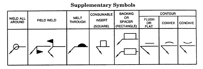
Common Supplementary Symbols
- Contour Symbols
- Finish Symbols
- Field Weld Symbol
- Backing and Spacer Symbols
- Melt-Through Symbol
5.1. Contour Symbols
Contour symbols indicate the desired shape or contour of the finished weld. They are placed above or below the weld symbol on the reference line.
- Flat (Flush) Contour: A straight line indicates that the weld should be ground or machined flat.
- Convex Contour: A curved line above the weld symbol indicates a convex (raised) shape.
- Concave Contour: A curved line below the weld symbol indicates a concave (recessed) shape.
5.2. Finish Symbols
Finish symbols provide instructions on how the weld should be finished. They are placed above or below the contour symbol (if any) and can include the following letters:
- G: Grinding
- C: Chipping
- M: Machining
- H: Hammering
- R: Rolling
5.3. Field Weld Symbol
The field weld symbol indicates that the weld is to be performed on-site rather than in a fabrication shop. This symbol is represented by a small flag at the intersection of the reference line and the arrow.
Example: Field Weld Symbol
5. 4. Backing and Spacer Symbols
Backing and spacer symbols indicate the use of a backing material or spacer to support the weld.
- Backing Symbol: A rectangular box placed on the reference line opposite the weld symbol.
- Spacer Symbol: A rectangular box with a vertical line through it, indicating a spacer.
5.5. Melt-Through Symbol
The melt-through symbol indicates that complete joint penetration is required and that the weld must penetrate through the entire thickness of the joint. This is represented by a filled circle or a square on the opposite side of the reference line from the primary weld symbol.
5.6. Combination of Supplementary Symbols
Often, supplementary symbols are used together to provide comprehensive instructions for the weld.
Supplementary symbols play a crucial role in conveying detailed welding instructions that go beyond the basic weld type and size. By understanding and correctly interpreting these symbols, welders and engineers can ensure that welds are completed to the required specifications, resulting in high-quality, reliable welded joints. Mastering the use of supplementary symbols is essential for anyone involved in the welding industry.
VI . AWS Weld Symbols
The American Welding Society (AWS) sets the standards for welding symbols in the United States. AWS weld symbols are widely recognized and used across the industry, providing a standardized method for conveying welding information. Understanding AWS weld symbols is crucial for ensuring welds meet the required specifications.

Basic Components of AWS Weld Symbols
- Reference Line: The main horizontal line that serves as the base of the welding symbol. All welding symbols are placed relative to this line.
- Arrow: Points to the joint to be welded. It can point to either side of the joint, indicating the location of the weld.
- Basic Weld Symbol: Indicates the type of weld required (e.g., fillet, groove, plug, slot, spot, seam, back, backing, or surfacing).
- Tail: An optional part of the welding symbol that can include additional information, such as welding procedures, specifications, or notes.
- Supplementary Symbols: Provide additional details about the weld, such as contour, finish, field weld, and backing.
Importance of Understanding Weld Symbols
- Clarity: Ensures clear communication of welding requirements between engineers, welders, and inspectors.
- Consistency: Promotes uniformity in weld quality across different projects and components.
- Efficiency: Reduces the likelihood of errors and rework by providing precise and standardized instructions.
- Safety: Ensures that welds meet the necessary strength and integrity requirements, which is critical for the safety and reliability of welded structures.
Practical Application
By mastering AWS weld symbols, welders and engineers can:
- Interpret welding drawings accurately.
- Execute welds that meet design and safety standards.
- Improve the quality and efficiency of welding processes.
- Communicate effectively within the welding team and with other stakeholders.
VII. Advanced Welding Symbols
As projects grow in complexity, so do the requirements for welding. Advanced welding symbols provide welders and fabricators with precise, detailed instructions for complex joints, multi-pass welds, and special conditions. These symbols go beyond basic fillet and groove notations, incorporating supplementary elements that ensure welds meet structural, safety, and performance standards. This section explores the intricacies of advanced welding symbols, their applications, and how to interpret them effectively.
1. Multi-Pass Weld Symbols
Description:
Multi-pass welds require several layers of welding to achieve the desired thickness, strength, or penetration. This is common in heavy-duty applications such as pipelines, pressure vessels, and structural beams.
Symbol Representation:
- A series of short, parallel lines (like “E” rotated sideways) placed along the reference line.
- Each line represents a single pass of welding material.
- Numbers beside the lines indicate the sequence of passes.
Application Example:
- Pipeline Welding: A groove weld requiring four passes may have four lines stacked on the reference line, ensuring weld strength and reducing internal defects.
2. Staggered Intermittent Welds
Description:
Staggered intermittent welds are used to distribute welds evenly across the joint, reducing warping and material distortion. This technique alternates welds on either side of the joint in a staggered pattern.
Symbol Representation:
- Two fillet weld symbols placed on opposite sides of the reference line with spacing (pitch) indicated by a number to the right.
- The pitch value indicates the distance between welds.
Application Example:
- Structural Beams: Staggered welds are applied to prevent distortion in large steel frameworks.
3. Melt-Through Symbols
Description:
Melt-through welds ensure full penetration, indicating that the weld metal must pass completely through the joint. This technique is crucial for joints subjected to high stress.
Symbol Representation:
- A solid black half-circle placed beneath the reference line.
- Accompanied by groove or fillet weld symbols.
Application Example:
- Pressure Vessels and Piping: Melt-through symbols are applied to ensure leak-proof welds that can handle high-pressure fluids.
4. Backing and Back Weld Symbols
Description:
Backing welds are applied before the main weld to provide support, while back welds are applied after the main weld to reinforce the joint from the opposite side.
Symbol Representation:
- A straight line (backing) or curved line (back weld) below the reference line.
- The curved line indicates a back weld applied after the initial pass.
Application Example:
- Shipbuilding: Critical joints may require backing welds to ensure full penetration without defects.
5. Field Weld Symbols
Description:
Field welds are those performed at the construction site rather than in a controlled workshop environment. These symbols notify welders that certain welds must be done in the field.
Symbol Representation:
- A flag placed at the intersection of the arrow and reference line.
Application Example:
- Bridge Construction: Field welds are used for assembling large structural components on-site.
6. Contour and Finish Symbols
Description:
Advanced projects often require specific weld contours (concave, convex, flat) to distribute stress and improve aesthetics. The method of achieving the desired contour is indicated by finish symbols.
Symbol Representation:
- Flat Contour (⎯) – Flat finish.
- Convex Contour (^) – Raised finish.
- Concave Contour (∨) – Indented finish.
- Finish Method Letters:
- G (Grinding)
- C (Chipping)
- M (Machining)
Application Example:
- Aerospace Components: Welds requiring smooth, polished finishes to reduce drag and fatigue cracking.
7. Non-Destructive Testing (NDT) Symbols
Description:
NDT symbols indicate that welds must undergo inspection using methods like radiographic (X-ray), ultrasonic, or magnetic particle testing. This ensures the weld’s internal quality without damaging the part.
Symbol Representation:
- NDT methods are placed in the tail of the welding symbol (e.g., RT for radiography, UT for ultrasonic testing).
- Specific welds may be marked with these symbols to highlight inspection points.
Application Example:
- Nuclear Power Plants: Welds in critical areas undergo ultrasonic testing to detect internal defects.
8. Multiple Reference Lines for Complex Welds
Description:
For joints requiring different weld types at the same location, multiple reference lines are used. Each line indicates a distinct weld process or pass.
Symbol Representation:
- The reference line closest to the arrow is the first operation.
- Additional lines above or below indicate subsequent operations.
Application Example:
- Offshore Platforms: Welds may require root passes, filler passes, and cap passes, each indicated on separate reference lines.
VIII. Conclusion
Welding symbols are an indispensable part of the welding process, serving as the universal language that bridges the gap between design intent and practical execution. By providing clear and concise instructions, welding symbols ensure that welds are performed accurately, consistently, and in compliance with engineering standards. This not only enhances the quality and durability of the final product but also minimizes errors, reduces material waste, and improves overall project efficiency.
From basic fillet and groove welds to advanced multi-pass and non-destructive testing symbols, understanding the full range of welding notations empowers welders, inspectors, and engineers to tackle complex fabrication projects with confidence. The ability to interpret and apply these symbols is a critical skill that ensures the integrity of structures across industries such as construction, aerospace, automotive, and oil and gas.
As technology evolves and industries demand higher levels of precision, the importance of mastering welding symbols will only continue to grow. By staying informed about the latest standards, participating in certification programs, and practicing symbol interpretation, professionals can ensure they remain competitive in an ever-advancing field.
In conclusion, welding symbols are more than just marks on a blueprint—they are the foundation of quality craftsmanship and safe, reliable structures. Mastering this visual language is not just a technical necessity but a gateway to professional excellence in the welding industry.
How to Read Tire Size
What is Oil Drilling? Key Steps in the Oil Drilling Process


 Automation System
  Energy Engineeing
  Instrumentation System
  Mechanical Engineeing
  Piping Technologies
  Transportations
  Manufacturing
  Training Material


