WELCOME TO PIPING TECHNOLOGY !!!

What is pressure relief valve ? How does pressure relief valve work

What is pressure relief valve ?

A pressure relief valve (PRV) is a type of safety valve used to control or limit the pressure in a system; pressure might otherwise build up and create a process upset, instrument or equipment failure, or fire. The pressure is relieved by allowing the pressurized fluid to flow from an auxiliary passage out of the system. The relief valve is designed or set to open at a predetermined set pressure to protect pressure vessels and other equipment from being subjected to pressures that exceed their design limits.

pressure relief valve

Components of pressure relief valve

The main components of a pressure relief valve include:

  1. Valve Body: The main structure of the valve that contains the internal components and provides the inlet and outlet connections to the piping or equipment. It is designed to withstand the full system pressure.
  2. Bonnet: The cover for the opening in the body of the valve. It can be bolted or threaded to the valve body and may house the adjusting mechanism for the set pressure.
  3. Spring: A crucial component that applies force to the valve’s closing mechanism (usually a disk or piston). The spring force is adjustable and determines the set pressure at which the valve will open.
  4. Disk or Piston: The component that seals the valve under normal operating conditions. It moves away from the seat to open the valve and allow fluid to escape when the system pressure exceeds the set pressure.
  5. Seat: The surface against which the disk or piston seals. The seat is usually made from a material that is compatible with the fluid and can provide a tight seal.
  6. Set Screw or Adjusting Nut: Used to adjust the spring tension, which sets the opening pressure of the valve. By tightening or loosening the adjuster, the set pressure can be increased or decreased.
  7. Lift Lever: A manual lever found on some pressure relief valves, used to manually open the valve for testing or to relieve pressure.
  8. Blowdown Ring: An adjustable feature that allows for the adjustment of the blowdown, which is the difference between the pressure at which the valve opens (set pressure) and the pressure at which it reseats (reseating pressure) after discharging fluid.
  9. Sealing Gasket: Ensures a tight seal between the valve body and the bonnet to prevent leaks.
  10. Guide: Aligns and directs the movement of the disk or piston within the valve body to ensure it seats correctly.
  11. Nozzle or Orifice: The passage through which the relieved fluid exits the valve. Its size and shape are critical for the valve’s capacity and performance.
  12. Overpressure Protection Device: Some valves may include additional mechanisms to protect against excessive overpressure in case the primary relieving device fails.

These components work together to ensure that the valve operates correctly, opening to relieve excess pressure and then reseating to maintain system integrity once normal conditions are restored.

Pressure relief valve symbol

The symbol commonly used to represent a pressure relief valve in engineering drawings and diagrams is a circle with a short perpendicular line or arrow extending from the top of the circle. This perpendicular line or arrow indicates the direction of flow or discharge when the relief valve activates. Sometimes, the symbol may include additional annotations or labels to specify the type or characteristics of the relief valve.

Here is a basic representation of the pressure relief valve symbol:

Pressure relief valve symbol

How does pressure relief valve work?

A pressure relief valve (PRV) works by automatically releasing pressure from a pressure vessel or system when the pressure exceeds a predetermined level, ensuring the safety and integrity of the system. Here’s a step-by-step explanation of how it operates:

  1. Normal Operation: Under normal operating conditions, the pressure within the system is below the set pressure of the relief valve. The force exerted by the spring (or other biasing mechanism) keeps the valve’s disk or piston seated against the valve seat, preventing the flow of fluid through the valve.
  2. Pressure Increase: When the pressure in the system starts to increase and approaches the set pressure of the relief valve, the force due to the system pressure acting on the disk or piston begins to counteract the force of the spring.
  3. Reaching Set Pressure: Once the system pressure exceeds the set pressure of the valve, the force exerted by the system pressure on the disk or piston overcomes the force of the spring. This causes the disk or piston to lift off the seat, opening the valve.
  4. Discharge of Excess Pressure: With the valve open, the excess pressure is vented through the valve’s outlet, reducing the system pressure. The discharged fluid is directed to a safe location, typically through a discharge piping system designed to handle the fluid safely.
  5. Re-seating of the Valve: As the pressure in the system decreases due to the release of excess pressure, the force exerted by the system pressure on the disk or piston diminishes. When the system pressure falls below the set pressure (minus the blowdown margin), the spring force pushes the disk or piston back onto the seat, closing the valve and preventing further discharge of fluid.
  6. Blowdown: The “blowdown” is the pressure difference between the set pressure (the pressure at which the valve opens) and the reseating pressure (the pressure at which the valve closes after having opened). It prevents the valve from chattering—a rapid, repeated opening and closing that can damage the valve. The blowdown is typically adjusted by a blowdown ring or similar mechanism in the valve.
  7. Reset for Next Cycle: Once reseated, the valve is ready for another cycle. It remains closed, maintaining a seal until the system pressure once again exceeds the set pressure.

The operation of a pressure relief valve is automatic and based on the balance of forces acting on the valve’s moving parts. It does not require any external control or intervention to function, making it a critical safety device in many pressure systems.

How to calculate flow of relief valve

Calculating the flow through a pressure relief valve involves understanding several key parameters and using specific equations tailored to the fluid type (gas, liquid, or steam) and the valve’s characteristics. The primary objective is to ensure the valve can relieve enough fluid to prevent a system’s pressure from exceeding its maximum allowable working pressure (MAWP). Here’s a simplified overview of the process:

1. Determine Fluid Properties

  • Type of Fluid: Gas, liquid, or steam, as the calculations differ for each.
  • Operating Conditions: Temperature and pressure of the fluid.

2. Valve Specifications

  • Valve Size and Coefficient: Obtain the valve’s effective area (usually given in square inches) and the discharge coefficient from the manufacturer’s data.

3. Set Pressure and Back Pressure

  • Set Pressure: The pressure at which the valve is designed to open.
  • Back Pressure: The pressure in the discharge system that can affect valve performance, especially for balanced bellows or pilot-operated valves.

4. Calculate Flow Capacity

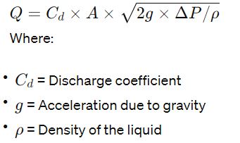
The general formula for flow capacity is:

Where:

  • = Flow rate
  • = Discharge coefficient (depends on the valve design and fluid type)
  • = Effective area of the valve’s orifice
  • = Pressure differential across the valve (set pressure minus back pressure)
  • = Fluid density at relieving conditions

For Gases and Vapors (Including Steam)

The flow of gases and vapors through relief valves is often calculated using the ideal gas law and factors to account for real gas behavior under certain conditions. The American Petroleum Institute’s API 520 and API 521 standards provide detailed methodologies for these calculations, including factors for adjusting for superheated steam or compressible fluids.

For Liquids

The calculation for liquids is more straightforward since liquids are incompressible. The formula simplifies to:

Calculate Flow Capacity Relief Valve

5. Adjustments for Real Conditions

  • Superheated Steam: Use specific formulas or correction factors for superheated steam, as it behaves differently from saturated steam.
  • Viscosity Correction: For liquids with high viscosity, corrections may be needed to account for the resistance to flow.

6. Safety Factors

Incorporate safety factors as recommended by standards and regulations, ensuring the valve can handle peak flows under emergency conditions.

Industry Standards and Guidelines

Refer to industry standards like API 520 (for sizing and selection of pressure-relieving devices) and ASME (American Society of Mechanical Engineers) codes for detailed methodologies and guidelines tailored to specific conditions and fluids.

For precise and accurate calculations, especially in critical applications, it’s essential to consult these standards and, if necessary, seek the assistance of a qualified engineer. The calculations can become quite complex, especially when dealing with mixed phases, reactions, or non-ideal behaviors.

Specifications when select pressure relief valve work

Selecting the right pressure relief valve (PRV) involves considering a range of specifications and factors to ensure the valve can adequately protect the system from overpressure conditions while meeting operational and regulatory requirements. Here are key specifications and considerations:

1. Set Pressure

  • The pressure at which the valve starts to open to relieve excess pressure. It is typically set at or just above the maximum allowable working pressure (MAWP) of the system it protects.

2. Capacity

  • The valve must be capable of discharging enough fluid to prevent the system pressure from exceeding the allowable limits. The required capacity depends on the system’s maximum flow rate under overpressure conditions.

3. Fluid Type

  • The nature of the fluid (gas, liquid, steam, or mixed phase) significantly influences valve design and material selection. The properties of the fluid, such as temperature, corrosiveness, and cleanliness, are crucial.

4. Size and Orifice Area

  • The size of the valve and the orifice area determine the flow capacity. The orifice size is selected based on the required flow rate to relieve excess pressure without exceeding the valve’s maximum flow capacity.

5. Temperature Range

  • The valve materials and design must withstand the minimum and maximum operating temperatures of the system.

6. Back Pressure

  • The pressure in the discharge system can affect valve performance. Valves are classified as conventional, balanced bellows, or pilot operated based on how they handle back pressure.

7. End Connections

  • The type (flanged, threaded, welded) and size of the valve’s inlet and outlet connections must be compatible with the piping system.

8. Materials of Construction

  • Material selection for the valve body, trim, seals, and other components must be compatible with the fluid and the operating environment to ensure durability and prevent corrosion.

9. Overpressure Allowance

  • The maximum overpressure the valve can handle while still operating safely, often expressed as a percentage of the set pressure.

10. Blowdown

  • The difference between the set pressure and the reseating pressure. Adjustable blowdown helps prevent valve chatter and ensures stable operation.

11. Operational Type

  • Whether the valve is spring-operated, pilot-operated, or uses another mechanism, which affects its responsiveness and suitability for various applications.

12. Certifications and Standards

  • Compliance with relevant industry standards (e.g., ASME, API) and certifications is essential for ensuring safety and reliability.

13. Reliability and Maintenance Requirements

  • Consider the valve’s reliability, ease of maintenance, and availability of spare parts.

14. Environmental and Safety Considerations

  • The valve should safely discharge the relieved fluid without harming the environment or personnel, requiring adequate discharge piping and, if necessary, treatment systems.

Selecting a pressure relief valve requires a comprehensive understanding of the system’s operational parameters, the characteristics of the fluid being handled, and the regulatory environment. It’s often advisable to work with experienced engineers or specialists and refer to detailed sizing and selection guidelines provided by standards and valve manufacturers.

Codes and Standards of pressure relief valve

Pressure relief valves (PRVs) are critical safety devices in various industries, designed to protect equipment, systems, and personnel from the dangers of overpressure conditions. The selection, sizing, and installation of these valves are governed by a comprehensive framework of codes and standards to ensure their reliability and effectiveness in emergency situations.

Key codes and standards that regulate the design, manufacture, and application of PRVs include:

  • ASME (American Society of Mechanical Engineers): ASME Boiler and Pressure Vessel Code, particularly Section VIII, which covers pressure vessels, including PRVs for such systems.
  • API (American Petroleum Institute): API 520 and 521 provide guidelines for the design and sizing of pressure-relieving devices in refineries, chemical plants, and related industries.
  • ISO (International Organization for Standardization): Various ISO standards apply to PRVs, including ISO 4126 for safety devices for protection against excessive pressure.
  • EN (European Norms): EN standards such as EN ISO 4126 also apply within European countries, harmonizing with international standards.

These standards ensure that PRVs are designed and tested to perform reliably under specified conditions, providing a critical safety function by venting excess pressure to prevent equipment failure, explosions, and other hazardous events. Compliance with these standards is essential not only for safety but also for regulatory approval and operational integrity of pressure systems.

In conclusion, pressure relief valves are indispensable in maintaining safe pressure levels in industrial systems. Understanding their operation, key components, and the principles behind their sizing and selection is crucial. Adhering to established codes and standards ensures that PRVs function as intended, safeguarding assets and lives against the risks associated with overpressure situations.

Pressure relief valve manufactures

There are numerous manufacturers around the world that specialize in the design, production, and supply of pressure relief valves (PRVs) for various industrial applications, including oil and gas, chemicals, power generation, and water treatment, among others. Some of the most well-known and respected manufacturers in the industry include:

  1. Emerson (Pentair Valves & Controls): Emerson’s range of PRVs, including those from its acquisition of Pentair, are widely used in various industries for their reliability and performance.
  2. Farris Engineering (Curtiss-Wright): Farris provides a wide array of pressure relief solutions and is known for its engineering expertise and custom valve solutions.
  3. Leser GmbH & Co. KG: A leading European manufacturer of safety valves, Leser offers a broad range of products for industrial applications.
  4. Consolidated (Baker Hughes): Consolidated safety valves are well-regarded for their quality and are used in multiple industries, including oil and gas and power generation.
  5. Crosby (Emerson): Crosby is another renowned brand under Emerson, known for its high-quality pressure relief valves and engineering support.
  6. Anderson Greenwood (Emerson): Anderson Greenwood offers a variety of pressure relief devices and is known for its innovative valve solutions.
  7. Kunkle Valve (Circor): Kunkle Valve provides safety and relief valve products for industrial and commercial applications, known for their durability and safety.
  8. Tyco Valves & Controls (now part of Pentair): Tyco offers a variety of valve products, including pressure relief valves, for various applications.
  9. Watts Water Technologies: Watts is known for a range of water safety and flow control products, including pressure relief valves for plumbing and heating applications.
  10. VELAN: A leading manufacturer of steel gate, globe, check, ball, butterfly, knife gate, and engineered severe service valves for critical applications.
  11. Weir Group: Weir provides a range of pressure control and relief valve solutions, especially for the mining and oil and gas sectors.

When selecting a PRV manufacturer, it’s essential to consider the specific requirements of your application, including the type of fluid, operating pressure and temperature, required certifications, and any industry-specific requirements. It’s also beneficial to assess the manufacturer’s reputation for quality, reliability, and after-sales support.

The different between pressure relief valve and safety valve
Pressure relief valves and safety valves are both types of pressure-relieving devices used in various industrial and engineering applications to protect equipment, systems, and personnel from overpressure situations. While they serve similar purposes, there are key differences between them in terms of their design, operation, and application.

Pressure Relief Valve:

  1. Function: A pressure relief valve is designed to relieve excess pressure from a system by opening when the pressure exceeds a predetermined set point. It is typically set to open gradually as pressure increases above the set point and closes when pressure returns to normal levels.
  2. Operation: Pressure relief valves operate in response to pressure changes within a system. They are designed to modulate flow, allowing for controlled release of fluid to maintain pressure within acceptable limits.
  3. Characteristics:
    • Typically used for applications where pressure control and regulation are required.
    • May have adjustable set points to allow for fine-tuning of pressure relief.
    • May incorporate features such as pilot-operated or proportional control for more precise pressure regulation.
  4. Applications:
    • Commonly used in systems where gradual pressure relief is desirable, such as in steam boilers, hydraulic systems, and process piping.

Safety Valve:

  1. Function: A safety valve is designed to provide rapid and full opening when pressure exceeds a predetermined set point, providing immediate relief from overpressure conditions. It operates as a last line of defense to prevent catastrophic failure of equipment or systems.
  2. Operation: Safety valves operate based on the principle of snap action, meaning they open fully and rapidly when pressure reaches or exceeds the set point. They are designed to provide immediate and unrestricted flow to quickly reduce pressure to safe levels.
  3. Characteristics:
    • Typically used for critical applications where rapid pressure relief is essential to prevent equipment damage or catastrophic failure.
    • Set points are fixed and non-adjustable, ensuring consistent and reliable operation.
    • May incorporate features such as lifting levers or visual indicators to indicate when the valve has opened.
  4. Applications:
    • Commonly used in high-pressure systems or applications where sudden pressure spikes could lead to catastrophic consequences, such as in steam boilers, pressure vessels, and gas storage tanks.

Key Differences:

  1. Operation: Pressure relief valves modulate flow to gradually reduce pressure, while safety valves provide rapid and full opening for immediate pressure relief.
  2. Set Points: Pressure relief valves may have adjustable set points, while safety valves typically have fixed set points.
  3. Response Time: Safety valves offer faster response times compared to pressure relief valves due to their snap action opening mechanism.
  4. Applications: Pressure relief valves are used for pressure control and regulation, while safety valves are employed in critical applications where rapid pressure relief is paramount to prevent catastrophic failure.

In summary, while pressure relief valves and safety valves serve similar purposes, their design, operation, and application differ significantly. Understanding these differences is crucial for selecting the appropriate valve for specific engineering and industrial applications to ensure optimal system safety and performance.

See more post here

Related posts
Gas Chromatographs: Comprehensive Insight into Principles, Components, and Applications

Contents1 Introduction2 What is gas chromatography used for ?2.1 Environmental Analysis2.2 Pharmaceutical Industry2.3 Food and Beverage Analysis2.4 Forensic Science2.5 Petrochemical Industry2.6 Clinical and Medical Applications2.7 Chemical Research2.8 Industrial Applications3 Fundamental Principles4 Components of a Gas Chromatograph4.0.1 Operational Aspects5 Carrier gas in gas chromatography5.1 Types of Carrier Gases for Gas Chromatograph5.1.1 Helium (He)5.1.2 Hydrogen (H2)5.1.3 Nitrogen […]
Read more
What is centrifugal pump? How does a centrifugal pump work?

Contents1 What is centrifugal pump?1.1 Introduction to Centrifugal Pumps1.1.1 Definition and Basic Principle1.1.2 Historical Development1.1.3 Common Applications2 Components and Design of Centrifugal Pumps2.1 Impeller Design and Types2.2 Casing Types2.3 Shaft, Bearings, and Seals2.4 Suction and Discharge Parts3 Operating Principles of Centrifugal Pumps3.0.1 The Physics Behind Centrifugal Action3.0.2 Fluid Dynamics in the Pump3.0.3 The Role of […]
Read more
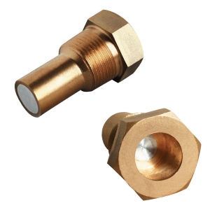
What is a fusible plug? How does it work?

Contents1 What is a fusible plug?2 What is fusible plug used for?3 Components of what is a fusible plug4 How does fusible plug work?5 Types of fusible plug6 What temp does a fusible plug melt at ?7 A fusible plug is made from8 Applications of  fusible plug9 Conclusion What is a fusible plug? A fusible […]
Read more
Sampling System : A comprehensive overview

Contents1 What is a sampling system ?2 Components of sampling system3 Online and Offline sampling system3.1 Online Sampling System3.2 Offline Sampling System4 Sampling Systems for Gas and  Liquide4.1 Gas Sampling Systems4.2 Liquid Sampling Systems4.3 Considerations for Both Systems5 Table to compare online and offline sampling systems6 Applications of Sampling system6.1 1. Chemical and Petrochemical Industry6.2 […]
Read more
Online Sampling Systems for Process Analyzers

Contents1 I. What is a Sampling systems in process analyzer?1.1 Key Functions of a Sampling System1.2 Components of a Sampling System1.3 Considerations for Effective Sampling Systems1.4 Considerations for Designing Online Sampling Systems1.5 Benefits of Online Sampling Systems2 II. Key Components of Online Sampling System3 1. Fast loop in sampling system3.1 Function and Purpose3.2 Components of […]
Read more
What is a Heat Exchanger?

Contents1 What is a heat exchanger?2 Types of Heat Exchangers2.1 Shell and Tube Heat Exchangers2.2 Plate and Frame Heat Exchangers2.3 Air Cooled Heat Exchangers2.4 Condensers and Evaporators Heat Exchangers2.5 Specialty Heat Exchangers3 Components of heat exchanger3.1 1. Tubes or Plates3.2 2. Shell3.3 3. Flow Configuration3.4 4. Inlet and Outlet Ports3.5 5. Baffles3.6 6. End Caps […]

Read more
The list of API Standards

Contents1 What is API standards of piping ?2 List of API standards of piping engineer3 API standards for offshore structure4 API standards for Valves and Wellhead Equipment5 API standards for Production Equipment6 The American Petroleum Institute (API) for Pipeline Operation7 The American Petroleum Institute (API) for Storage Tank Safety8 API standards petroleum standards8.1 Exploration and Drilling8.2 […]
Read more
Boiler pressure relief valve overview

Contents1 Introduction Overview of boiler systems and boiler pressure relief valves (PRVs)1.1 Definition of a Boiler Pressure Relief Valve1.2 Function of a Boiler Pressure Relief Valve1.3 Prevention of Overpressure Conditions2 The Need for Pressure Relief in Boilers2.1 How Pressure Builds Up in a Boiler System2.2 Potential Risks Associated with Excessive Pressure3 Components of a Boiler […]
Read more
What is pressure transmitter ? Working principle of pressure transmitter

Contents1 What is pressure transmitter ?2 What are the components of a pressure transmitter?3 Working Principle of pressure transmitter4 Types of pressure transmitters4.1 Advance and Disadvantage of each types of pressure transmitter4.2 Absolute Pressure Transmitters4.3 Gauge Pressure Transmitters4.4 Differential Pressure Transmitters4.5 Sealed Gauge Pressure Transmitters4.6 Multivariable Transmitters4.7 Capacitive Pressure Transmitters4.8 Piezoelectric Pressure Transmitters4.9 Strain Gauge […]
Read more
What are petrochemicals? Overview process and layout of Petrochemical Plant

Contents1 What are petrochemicals?2 Overview outline of what are petrochemicals plant3 Petrochemicals plant technologies4 The products of petrochemical factory4.1 Primary Petrochemicals4.2 Secondary Petrochemicals4.3 Specialty Chemicals and Products5 Petrochemical Processing – From Raw Material to Final Usage5.1 1. Extraction of Raw Materials5.2 2. Separation and Refinement5.3 3. Primary Petrochemical Production5.4 4. Intermediate Chemicals Production5.5 5. Specialty […]

Read more